THE JOWETT CAR CLUB OF AUSTRALIA INC.
Associations Incorporation Registration Number: A9664E
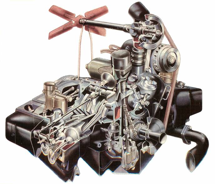
Engine diagram courtesy of ‘The Motor’, May 21st, 1947.
With thanks.
AN INTRODUCTION TO OVERHAULING THE JOWETT JAVELIN/JUPITER ENGINE
CONTENTS
Topic Discussed Page No.
Foreword 3
A Note About Gaskets 14
Big End Bearings 9
Camshaft And Timing Chain 11
Clutch Housing 14
Conclusion 15
Connecting Rods 9
Cost Of An Engine Overhaul 3
Crankshaft 8
Cylinder Heads 12
Cylinder Liners 10
Dismantling The Engine 5
Engine Oil Filter 12
Engine Oil Pump 11
Examining The Engine 4
Flywheel 14
Front Timing Cover 11
Hand Tools 5
Installing The Rear Timing Cover Gasket 15
Jowett Engine Types 4
Locating Dowels 8
Main Bearings 9
Pistons 10
Rear Main Oil Seal 14
The Crankcase Set 6
![]()
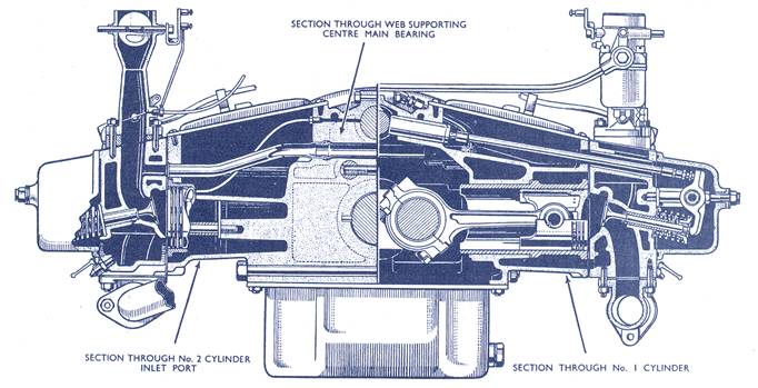
A Series Of Cross Sections Through The Jowett Engine
JOWETT TECHNICAL NOTES
AN INTRODUCTION TO OVERHAULING THE JOWETT JAVELIN/JUPITER ENGINE
![]()
Foreword
Having purchased a Jowett Javelin or a Jowett Jupiter, both of which use basically the same engine, it is worth advising here, that these motorcars are exceptional. A great number of their design features are purely Jowett. The Javelin and Jupiter models employ an engine that is unique to them. It is, most definitely, an engine that is worth overhauling.
For the person who attempts an overhaul of a Jowett Javelin/Jupiter engine, for the first time and having listened to some deprecatory comments from ill-informed sources, it can be a very daunting prospect. This set of notes attempts to help the Jowett novice come to terms with the minor eccentricities of the Jowett flat four engine, as used in the Javelin and Jupiter motor cars. Hereafter called the ‘Jowett engine’ for convenience.
This booklet is intended for distribution to members of the Jowett Car Club of Australia, for their use when considering, and during, an engine overhaul. It should be used in conjunction with the Jowett Maintenance Manual that suits the vehicle being overhauled and the works Service Bulletins, which have been reprinted.
It must be emphasised that this booklet does not replace the Maintenance Manual published by Jowett Cars Limited.
Reference is made, in these notes, to other non-Jowett Cars Limited publications. They are available to members of the Jowett Car Club of Australia. Orders for these booklets and reprinted Service Bulletins should be placed with the club’s Spares Officer.
Important note: If the vehicle’s owner decides to use the services of a proficient specialist workshop, then it is strongly advised that this book be made available to that organisation. It is very important that workshop staff have a good understanding of these notes.
Availability of spare parts for the Jowett engine, though readily catered for, has reached the state where parts can not be seen as expendable, or being scrapped due to taking an improper course of action, any more.
There is nothing particularly difficult with respect to overhauling a Jowett engine, however it does have some idiosyncrasies that, with more than fifty years of experience, can now be better explained.
The assembly of a Jowett engine requires a certain amount of skill. It is not the same as a Holden Red Engine, where machined items are simply assembled with a torque wrench. Reading everything available on the engine’s rebuilding is important and necessary. Putting all of the gleaned information into practice needs constant vigilance, patience and mechanical skill to avoid disappointment. If these requirements are not available, then careful selection of someone who has these skills should be enlisted to provide assistance.
It should be remembered that the most recent ‘works’ technical information published by Jowett Engineering Limited, was probably issued in 1963, and that would have been only in reference to specific items.
The Jowett engine did suffer from being too advanced for its time. It should be remembered that, at that time, both the British and North American motor industries were heavily involved with the use of cast iron for major engine components. Jowett Cars Limited, who used aluminium for the crankcase, made an ambitious step. There were other aluminium crankcases manufactured by Jowett, but these were of the separate cylinder block to crankcase configuration. The Jowett engine, discussed here, was the first manufactured by Jowett to use aluminium for a wet cylinder liner type of horizontally opposed engine. It also had a joint along the centre – this was another first for Jowett Cars Ltd.
The Jowett Javelin was introduced in 1947, at a time when most garage mechanics and vehicle owners were not familiar with the use of aluminium for a major component such as a crankcase set. Indeed, this was still the case in the early 1960s when the Hillman Imp was released to the public, it having an engine in which aluminium played a very major role.
A major consideration with respect to the Jowett engine, is to reflect on “who has been there before?” and, “with what skills of workmanship?” In many cases, it would be nice to know – then perhaps it wouldn’t!
Having a properly overhauled and tuned Jowett engine can give great satisfaction to the person who has done all that careful work. It should, with proper servicing and maintenance, give a long and totally reliable life.
For convenience, these notes are divided into sections dealing with the major components. In these notes, the terms ‘RHS’ and ‘LHS’ refer to components observed from the drivers seat, looking forwards.
Cost of an Engine Overhaul
In these times, overhauling an engine can be considered very expensive. This does not only apply to the Jowett engine, but to others that are much newer and spare parts are still manufactured in vast numbers.
To fully overhaul and modify a Jowett engine, the total cost can be in the region of $8,000 to $9,000. In many cases this is seen to be more than a good Javelin is worth. This is probably a true assumption, but this cost can also, in the long term, be seen as an investment. As more Jowett Javelins and Jupiters are seen to be totally reliable, their values will certainly rise.
Obviously, the amount of work and cost invested in a Jowett engine is entirely the owner’s decision. Engines can be partially overhauled successfully at minimum cost. However, if long distances at semi high-speed running are being considered, then more expensive engine overhaul procedures should play a major role in that consideration.
It should also be borne in mind that repairs that are seen to be expensive with respect to a Jowett engine, are just as expensive – if not more so – when applied to engines from other manufacturers. The cost of machining an earlier model crankcase set towards the Series III type is approximately $900.00. To modify an oil pump and enlarge the oil galleries will cost approximately $250.00. These machining operations should be considered as worthwhile investments.
Reading the period motoring writers’ test reports on the Javelin and Jupiter models, it can immediately be observed that the cars received excellent reviews and test reports. It was the public’s perception of unreliability that really stuck. It is our club’s task to turn that perception around.
Jowett Engine Types
With the introduction of this engine, Jowett Cars Limited experienced, very likely, the steepest learning curve in the motor industry. The company had manufactured a similar four cylinder horizontally opposed engine in the 1930s. In the situation with respect to the Javelin and Jupiter power units, the type of construction was very different. Until the introduction of this engine, all Jowett-built horizontally opposed engines had separate cylinder assemblies bolted to a one-piece aluminium crankcase and they were all of low compression ratio side valve configuration. The engine described here was Jowett’s first production unit with a split crankcase that housed wet type cylinder liners, featured overhead valve operation and used a crankshaft entirely machined from a billet of steel running in direct mounted bearing shells. It was also the first high performance engine built by Jowett Cars Limited.
There were two distinct versions of the Jowett engine – the first version and the second version, which is called the Series III engine. However, engine type description is not that simple, because Jowett Cars Limited in their wisdom, had a procedure that ‘blended-in’ engineering changes throughout the engine’s production life. Some engineering changes had their own changes ‘blended-in’ within their span of use.
All engines feature a raised plinth on the front face of the LHS crankcase half. The number stamped on to this plinth informs of the year of manufacture, the type of vehicle, the production series and the engine’s actual serial number. A sample identification number could be:
E1 PC 12782 This can be explained as follows:
E = the decade, i.e. 5 (A = 1, B = 2 and so on)
1 = the year in the decade
P = passenger vehicle (Identifies a Javelin)
C = production series (third)
12782 = Number of engines built
This serial number identifies a 1951 Jowett Javelin of the third production series.
An example identification for a Jupiter engine could be:
E0 SA 42R This can be explained as follows:
E = the decade, i.e. 5 (A = 1, B = 2 and so on)
0 = the year in the decade
S = sports vehicle (Identifies a Jupiter)
A = production series (first)
42 = Number of engines built
This serial number identifies a 1950 Jowett Jupiter of the first production series.
Production series identification was updated when a significant number of engineering changes had been introduced. This usually took place in October of each year, due to new models being announced at the Earls Court Motor Show, in London. A car produced immediately after the motor show could carry the next year’s identification code – all new models introduced at the show being classed as the next year’s model.
The crankcase set numbers, stamped into the upper front faces, are not the same as the engine’s serial number, though some can be close, as the engine’s serial number was not allocated until the engine was prepared for the vehicle receiving it.
Examining the Engine
An engine that is being considered for an overhaul will probably be in a neglected state. It will be covered in dust that has clung to leaking oil, or will have some wet areas where oil has leaked.
Inspection of an engine, before dismantling is very important. This helps to determine areas that require closer inspection during and after the dismantling process. If there is a presence of oil in the two valleys in the top of the crankcase assembly, several areas require further investigation. Common leakage points are:
· The joint between the front and rear timing covers. Often an attempt is made at repairing an oil leak here, by removing the rear timing cover and inserting a new segment of the front timing cover gasket. This practice never works well.
· Small piece of felt (rubber) missing from joint at crankcase.
· Gasket between rear timing cover and crankcase has hardened with age and broken due to engine oil pressure action.
· Filter canister sealing ring hard or broken.
· Lack of a good quality fibre washer at the oil filter drain bolt.
· Fatigue cracks in the Vokes (green wrinkle paint finish) oil filter canister at the closed end due to over-tightening of canister bolt.
· Loose fit of breather valve pipe where it exits crankcase.
· On later engines, the fibre washers at oil cooler connection banjo bolts.
· Top central joint of crankcase due to burrs, loose bolts or lack of washers under bolts and nuts.
Other common oil leakage points on a Jowett engine are as follows:
· Loose dynamo mounting bracket. This bolt, and one of the cooling fan stay bolts’ threaded holes break through into the oil-wet area.
· Absence of breathing felts in tappet chest covers.
· Failure of the positive crankcase ventilation valve.
· Hard rubber seals at the rocker covers.
· Absence of sealing washers (grommets) at the rocker covers studs.
· A worn front crankshaft pulley where seal lip is in contact. Seal could have hardened lip due to age.
· A worn rear crankshaft spigot where rear main oil seal runs. Seal could have hardened lip due to age.
· Petrol pump gasket, due to – hard gasket, warped flange, or fastening setscrew stripped.
· Absence of gasket between flywheel housing and crankcase.
· Oil migration from bolt and stud threads that break through into oil-wet areas inside crankcase.
· Excessive blow-by from worn piston rings etc.
· Push rod tubes in cylinder heads not secure fit.
· Fit of oil filler tube into front timing cover.
· Sump gasket hard and porous. Stripped threads in sump surface of front timing cover. Sump drain plug gasket broken.
· Oil pressure pipe fitting loose in rear timing cover.
Investigative examination should reveal why an oil leak exists – cracks, gasket damage or misalignment.
It should be noted that Jowett engines run fairly high oil pressure. This is normally between 50 psi (345 kPa) to 75 psi (517 kPa) and it is therefore important that good assembly procedures be used to ensure that leakage points are properly sealed. It is good practice to use good quality flat stainless steel washers, red fibre washers of proper fit bearing on smooth clean surfaces. Using such techniques can ensure a leak-free engine that is achieved with minimal use of sealants.
Prior to dismantling the engine, it should be thoroughly cleaned and dried. It can be said that, “If there is still grime on the outside, then it will certainly migrate into critical areas on the inside too!” Then further inspection can be carried out during and after dismantling.
Hand Tools
Almost exclusively, Jowett Cars Limited adopted BSF threads. There are few exceptions in the Javelin and Jupiter motorcars; the flywheel push-off bolt threads are BSW and the lock bolt for the belt tension adjuster at some dynamos has UNC thread form. The thread for the breather valve assembly, where it is screwed on to the oil filler tube is of SAE origin. Smaller sizes, as used at the carburettor linkage are British Association (BA) thread forms.
Therefore, it is of vital importance that the correct size spanners and sockets are employed when working on a Jowett engine. SAE and metric size spanners and sockets should no be forced onto BSF sized bolts and nuts. In addition, loose fitting spanners and sockets should not be used. There is no substitute for using the correct size spanners and socket tools.
BSF (BSW) spanner sets and sockets can be obtained new, with a little perseverance. It is still possible to buy the Stahwille and Gedore brands in BSF sizes. They would probably have to be ordered. Good quality tools can also be found at swap meets. However, great care needs to be taken when purchasing in this situation. There are many instances where BSF open-end spanners have been enlarged by crude filing, to suit SAE and metric sizes. The situation here is buyer beware!
The most common BSF sizes used on the Jowett engine are – 3/16”, ¼”, 5/16”, 3/8”, 7/16” and ½”. In addition 9/16”, 5/8” and ¾” sizes are used for chassis hardware. Bolt terminology used here means that the term ‘bolt’ indicates that it is a hexagon headed bolt with a plain nominal size shank and proportional length of thread. The term ‘set screw’ indicates a hexagon headed screw with a thread along its entire length.
Special tools can be of great help when working on a Jowett engine.
1. A cylinder head pulling tool – this is a must, because of severe damage that can be inflicted by levers at the crankcase surfaces. This is a simple tool, that can be made-up from a piece of flat steel bar 5½” (140 mm) long by 1½” (38 mm) wide by 5/16” (8 mm) thick. See sketch in Appendix 1. The flat bar should have two 3/8” diameter holes to accommodate the two rocker post studs, after the rocker assemblies have been removed. Use suitable spacers so that the tool bears against cylinder head stud number 1. This stud protrudes higher above the cylinder head surface than the others. Use two rocker stud nuts to force the cylinder head away from the crankcase surface cleanly and squarely without any effort.
2. Another useful tool is an engine stand as shown in the Jowett Maintenance Manual. Use of this stand will save your back and will also allow you to view the engine at good eye level.
3. An individual crankcase stand. This allows the crankcase half to be worked on while resting on the cylinder head surface. This support can be easily made from a 4” (100 mm) block of wood. Use a head gasket as a pattern to drill the cylinder head stud holes. Use a 7/16” or ½” drill for this. For safety, the block can be clamped to the workbench surface.
4. A worn starter ring gear can be used to facilitate locking of the crankshaft for unscrewing flywheel bolts and the starting handle dog bolt. Cut a section out of the ring gear about 2” (50 mm) long, cut at an angle at one end so that as the teeth are engaged with the ring gear on the flywheel, the tool becomes firmly wedged between the flywheel and its housing. This tool can be inserted at the starter motor opening.
Other specialist hand tools such as piston ring clamp and three-legged puller can be purchased from a good tool retailer.
Dismantling The Engine
One point to be aware of right at the start is that the crankcase tie-bolts and studs are located in pairs in the three main bearing supports. There are two tie bolts and trunnion nuts in the front support. There are two threaded tie-rods with two nuts each, located below the crankshaft centreline, at the centre and rear supports. At the lower front there is a tie bolt and trunnion nut and, for socket access, the RHS engine mount bracket will need to be removed first. Above the crankshaft centreline are three tie-bolts and trunnion nuts. The centre upper bolt is located inside the LHS tappet chest. This is the hidden tie-bolt. To gain access to the upper rear tie-bolt with a socket, the rear water inlet will have to be removed first.
Before removing the clutch pressure plate, check that there is a letter stamped into the clutch housing and into the flywheel face at one of the clutch locating dowels. This indicates a balanced group and the letters will be either “A” or “X”. Currently, these markings cannot be trusted, as components may have been swapped during repairs. After removing the clutch pressure plate, by loosening and removing the six bolts in turn, the flywheel bolts should be removed. There are two 3/8” BSW threads provided for all thread set screws to push the flywheel from its spigot at the crankshaft. High tensile 3/8” UNC set screws can be used successfully.
Extreme care must be exercised when removing the bronze gear wheel from the crankshaft nose. The teeth can be easily broken. It should be noted that the large radius in the gear wheel’s bore, faces the front main bearing journal.
The Jowett engine, if in reasonable condition, comes apart very easily, therefore if resistance is found; do not use force until the situation has been examined thoroughly. Use of unnecessary force can cause severe damage to engine components.
The Crankcase Set
The most important initial check to make is that the two halves of the crankcase set are a matched pair. This can be checked easily by reading the crankcase set numbers located on the upper front faces. These numbers are usually not as prominently stamped as the engine’s serial number on the plinth. It is vitally important that a crankcase set has matching numbers.
There can be considerable variations from set to set, and mixing them could produce some remarkable differences in alignments at joint faces and bearing bores. In Britain Jowett Engineering Limited would save intact halves of crankcase sets for future use as what are now commonly known as ‘odd-half-crankcase sets’. Such sets had extra numbers and the code ‘OS’, meaning the main bearing and camshaft tunnel bores were oversize – to the extent of being 0.040” oversize. This condition was quite in order at the time, during the late 1950s to early 1960s. However it is now a severe burden as the thicker main bearing shells are no longer available. The same applies to camshafts with larger journals.
Generally, there were no odd half crankcases supplied to Australia. However, there could be later (private) imports of such crankcase sets.
Essentially, crankcases identified as PA, PB, PC, PD, SA production series are the early type. Crankcases identified as PE and SC are of the Series III engine type. With respect to the Javelin, some PD identified engines could be of the Series III type. With the Jupiter, the case is more clear-cut, as there was not a SB model so all SC Jupiters did have Series III crankcase sets – but a few SA models also were fitted with Series III sets. This can be confusing, but there are other means of identifying the crankcase set type. In Australia, the majority of engines were pre-Series III.
It should be noted that a Series III engine in Australia could have a special serial number – E3 PE JKD 206 or simply JKD 106 (locally assembled vehicle).
The Series III crankcase set can have a ‘3’ stamped into the RHS top face adjoining the rear timing cover. It also has extensive cross bracing at the crankshaft main bearing support webs. Other identifying points are the larger oil feed galleries to and from the rear timing cover (although the last few of the early engines did have this feature), the raised longitudinal oil galleries that did not break through severely into the tappet bores, shouldered brass plugs in the ends of the upper two oil feed galleries and pressure relief drillings in the sides of the blind cylinder head stud holes. Probably, not all Series III crankcases have this last feature.
It is most important that the truth of the main bearing tunnel bores is properly measured. The tunnel diameter can be distorted by three common factors – by over-tightening the crankcase tie-bolts, by oil starvation to one main bearing and by twisting action due to a broken crankshaft.
If the crankcase set is of the early type, it can be partly converted to Series III by machining as described in Technical Notes Series – Crankshaft Bearings. It is also a good idea to enlarge the oil feed to the filter gallery. Obviously, the corresponding gallery in the rear timing cover should be enlarged also. Typically the oil feed gallery is 5/16” (8 mm) diameter feeding two ¼” (6 mm) galleries. The delivery gallery bores can be opened out to 7/16” (11 mm) diameter.
If the delivery gallery is enlarged, the oil pump delivery pipe, banjo and elbow should be enlarged as well.
In some cases the LHS gallery that connects with the longitudinal gallery is located very close to the rear timing cover fixing bolt threaded hole. This condition means that there could be oil leakage to the fixing bolt area. A machine shop can mill out an offset bore large enough and deep enough to permit a suitable aluminium plug to be pressed in. the plug should be sealed with Loctite adhesive. A new gallery-connecting bore can be marked out 0.080” (2 mm) further away from the threaded hole and drilled through.
When this is being done, the oil feed gallery to the rear main bearing can be enlarged to 5/16” (8 mm) diameter to provide more oil to the rear main bearing and number 4 crank pin.
Along the top central ridge edges there are five ¼” bolt holes. In some instances, these holes may have broken through the inside face of the joint flange. The bolt shanks are then exposed to an oil-wet area in the crankcase. This condition can cause oil leakage along the bolts’ shanks, through the spring washer and past the nut. The fix for this concern is to install the bolts with sealant, good quality flat washers and Nyloc nuts.
All threaded holes should be thoroughly checked for threads that have been stripped. It is vital that all threads are in good condition. Thread inserts, such as Helicoil or Recoil, successfully repair damaged threads. Stripped threads can be common in Jowett engine crankcases, perceived to be due to the use of the BSF thread form. There was nothing wrong with this design, provided that the threads in the castings are sound and correct torque values are carefully used during the assembly process. Commonly stripped threads can be found at the rear timing cover bolts, water inlet flange studs, oil pump studs, petrol pump bolts and timing cover bolts.
In the engine’s original use period, cylinder head gasket failures were reasonably common. This frequently resulted in excessive strain being applied to the cylinder head studs, to the extent that aluminium could give and ‘rise’ adjacent to the shoulder of the stud. This can also result if a stud is over tightened into the crankcase. In the event of such a condition, the thread hole can be drilled and a Recoil insert installed. The threaded hole for cylinder head studs can also be counter bored to a depth of 3 mm, to the stud’s shank diameter to provide a snug fit. All studs should be installed by tightening into the crankcase to 40 per cent of the stud’s assembled clamping torque value at final assembly. This 40 per cent value is an industry specification.
The crankcase set must be tested for cracks. Common areas where cracks can be found are at the rear face running from the water inlet bore outwards to the head gasket face, cracks can be found inside the tappet chest on either side of the oil feed stud. Another area where cracks can be found is along the top joint flange. It has also been reported that cracks can appear adjacent to the centre camshaft bearing bore.
These cracks sound alarming, but most are the result of incorrect assembly (and dismantling) processes. The most common cause of cracking is having excessive cylinder liner protrusion above the cylinder head gasket surface. The cause of cracks in the upper joint face is usually due to attempts to lever the two crankcase halves apart, with the upper centre tie-bolt remaining in situ. Another cause can be connecting rod breakage.
Jowett engine crankcases are easy to weld, but care needs to be taken with respect to distortion.
All gasket face joints for the oil sump, front timing cover, rear timing cover and clutch housing must be flush and have good flat surface finish.
The three main bearing supports faces, on each crankcase half, must be absolutely flat and free from burrs. Careful attention should be paid to this, as engine oil pressure is present at these faces. A burr could allow large amounts of oil to escape prior to reaching the crankshaft bearings. Another point to investigate here is that the upper joint face is absolutely flush with the main bearing supports, along its entire length.
At the rear main bearing it is strongly recommended that separate thrust bearings be installed. This ensures that all three main bearings have the same surface metal, are finished to the same dimension and that there is better control of crankshaft end float.
The installation of separate thrust bearings is described in Technical Notes Series – Crankshaft Bearings.
Great care should be taken to ensure that the main bearings have the correct amount of crush, 0.0025 (0.063 mm), exerted upon them when the crankcase tie-bolts are tightened to the correct torque value. Loose bearing shells will cause main bearing rumble and loss of oil pressure.
The camshaft bearing bores should be checked for wear. It has been reported that the centre bearing bore wears at a faster rate than the other two. There is an option for effecting a sound repair. The camshaft bores can be tunnel bored to an oversize dimension, and the hard chrome process can build up the camshaft journals. It is also feasible to have a camshaft manufactured with oversize journals; it is a simple shaft with no complicated skew gear forms.
Camshaft end float can cause a harsh knocking sound, particularly at low engine speeds. A method of reducing this phenomenon is to introduce a 1/16” (1.6 mm) chamfer at the front joint face edges. The edge chamfer should extend above and below the front camshaft bearing bore to the extent that it just protrudes beyond the outer diameter of the camshaft thrust flange. These chamfers allow oil pressure to escape in a controlled manner. See diagram in Appendix 1.
A vital element of Jowett engine assembly is the installation of the internal carburettor balance pipe. The correct size seal rings must be used. Seals of incorrect fit or that have been cut or damaged while joining the two halves of the crankcase set, will cause the symptom of excessive oil smoke at the exhaust. Another element that affects the soundness of the internal balance pipe is web clearance when installing a Laystall crankshaft for the first time. The big end journal throw adjacent to the carburettor balance pipe can, in some instances, actually clash with the pipe to the extent that a hole will be very quickly cut through. This condition also results in great amounts of oil smoke. The internal balance pipe can be dented in the area of the crankshaft’s arc to provide suitable running clearance.
It should be noted that, during assembly of the two crankcase halves, great care should be taken with the installation of the internal balance pipe seals. New sealing rings should be used and note must be made of removing the old seal rings and cleaning the pipe bores during the crankcase cleaning process.
When installing the internal balance pipe seals, the trick is to allow the seal ring to roll itself into the space provided. Thus merely install the seal ring squarely on the pipe at the outer end portion, so that when it is pushed into the crankcase it will roll until it butts up against the shoulders.
Furthermore, extra care must be taken when installing the internal balance pipe seals into a Series III crankcase set. The bore for the pipe and seals passes sharper edges in the centre main bearing support, a sharp edge here can cut the seal rings.
The crankcase tie-bolts must be torqued to the correct value during assembly. Sealant, such as Loctite Master Gasket 518, should be used only along the top joint faces. It should not be used at the main bearing support faces.
It is a good idea to do a ‘rehearsal’ assembly of the two halves without the balance pipe seals, but with the crankshaft to verify bearing clearances, shaft end float and running clearance.
During final assembly, the crankcase halves must be spotlessly clean. The crankcase tie-rods must have good quality flat washers that seat on smooth spot faces. Dowty type washers, with a flexible sealing lip bonded to the bore, can be used successfully in this area. Dowty washers can be purchased from hydraulic component suppliers. It should be noted that all three upper crankcase tie-bolts pass through the oil feed galleries to the main bearings. The oil pressure here can exceed 60 psi (414 kPa), thus needing perfect sealing faces under the flat washers and tie-bolt heads.
All studs should be secure; those that have threaded holes that break through into oil-wet areas should be installed with sealant on their threads.
Locating Dowels
The Jowett engine is equipped with several locating dowels, which hold components in proper alignment with each other. Located at the top front and rear of the crankcase halves, are two steel dowels that locate in precision located steel bushings pressed into the crankcase parent metal. These dowels are not a particularly tight fit in their bushings. They can fall out during crankcase disassembly, and then be forgotten.
There are two dowels, one in each crankcase half front face, for locating the front timing cover. These dowels usually remain in the crankcase components. They are important because they help to tie in the front crankcase joint and also locate the front timing cover flush with the sump gasket face at the crankcase. If a different front timing cover is being used, a dummy assembly of the components should be made to ensure that surfaces are flush with each other.
At the rear of the crankcase set, there are two hollow dowels that locate the flywheel/clutch housing to the crankcase set. These dowels can remain in the crankcase halves, or they can remain in the flywheel/clutch housing. Care needs to be taken to note this condition if a different flywheel/clutch housing is going to be installed. These two dowels perform the same functions as those in the front face previously mentioned.
Other dowels are the main bearing shell locating dowels. These should locate firmly in the crankcase bores and should not at any time protrude through the bearing surface material on the bearing shell. These dowels feature an axial drilling so that a grease gun, with a point type nozzle, can be used to force the dowels out. The number of these dowels can vary with the type of crankcase.
Located in the front RHS crankcase face are two hollow dowels that locate the engine oil pump. The importance of these two dowels cannot be over stressed. They control the mesh of the oil pump drive gears. If the dowels are missing, the oil pump can move to the extant that the gears can have an out-of-mesh situation and the ignition timing value can be lost. Again, these dowels can remain in the crankcase or they can come away with the oil pump when it is removed.
There is a master dowel in the rear face of the crankshaft. This dowel ensures that when the 1 & 2 top dead centre marking on the flywheel rim is aligned with the crankcase set upper joint line, crank throws for 1 & 2 cylinders are actually at top dead centre. It is possible to force one of the threaded holes (for pusher set screws) over the dowel. Doing this will cause great confusion with system timing set up and cause an imbalance situation between crankshaft and flywheel.
There are steel bushings pressed into the bottom surface of the crankcase set. These were provided for machine location purposes during crankcase production. They are not used for engine assembly procedures.
Dowels are present in motor vehicle components to serve a vital function. It can be guaranteed that if they were not absolutely necessary, then Jowett Cars Limited in their thriftiness would certainly not have used them in the first place!
If a dowel is found to be loose, then the proper procedures must be used to rework the component so that they are a good fit. This will probably require the services of a good machine shop with suitable jig boring equipment. Adhesives and sealants should not be used to secure loose dowels.
Crankshaft
Firstly, it should be noted that all engine crankshafts have a ‘use-by’ date. It is just unfortunate that in the case of some, this date is sooner than for others. With respect to the Jowett engine, crankshaft breakage in the early days was fairly common. It is interesting to note that other brands do break their crankshafts, but the fact is not spread so wide and far.
There were several stages in the development of the Jowett crankshaft and, generally, it can be stated that if the shaft is of the flat web type, it could be severely cracked. It is not recommended that use of this type of shaft be made. The final style of crankshaft is known as the oval web shaft. This shaft can be identified by the facts that the webs are fully machined, there is a date code stamped into the shaft and there is the maker’s trading name, ‘Laystall’ with an oval ring around it, stamped into the shaft. Care needs to be taken when identifying an oval web crankshaft because there were some cast iron shafts manufactured in Australia by a company in Adelaide. These shafts look similar to the Laystall shaft; except for casting flashes and the sand grain finish of the webs.
The Laystall oval web shafts need to be placed in two groups – those made prior to 1959, and those made after that date. The early Laystall shafts should not be hardened by the nitriding process; the later type should be thus hardened. The nitriding process is described in the Technical Data Notes for Javelin and for Jupiter.
The key to a long and reliable life for a Laystall and a cast iron shaft (Mead) is to ensure that the main and big end journals have a 0.100” radius at each end. This is the fundamental requirement for long crankshaft life. A nitrided Laystall crankshaft should be finish ground, because the journal diameters can ‘grow’ during the hardening process. Failure to do this will result in a locked crankshaft after assembly.
To make an initial assessment of the soundness of the crankshaft the ‘ring’ test should be applied. Suspend the crankshaft on a wire loop tied around the starting handle dog bolt. A smart tap on the web with a small hammer should elicit a clear ringing tone. This indicates that there are no cracks in the shaft. If the tone is a dull thud there is a clear indication that the crankshaft is cracked.
All crankshafts must be properly crack tested prior to commencing any work on them. They can be successfully ground to 0.050” undersize. Only use a reputable crankshaft repairer who acts explicitly on instructions. Make sure that it is understood that the rear spigot face where the flywheel attaches is not ground, to clean up the seal lip surface. Otherwise it will not be possible to keep the flywheel bolts tight.
The front shaft extension for oil pump and camshaft drives must be concentric with the three main bearings.
The group comprising the crankshaft, flywheel, clutch assembly with six of the same-make attaching bolts, and front pulley should be balanced as a group. Jowett Cars Limited balanced the crankshaft and flywheel as a group in production – but fifty years later, it is not known if these components are still a balanced pair.
Main Bearings
The main bearings in the Jowett engine were initially shells lined with white metal. Very early on, there were concerns with this material, which failed due to heat and stress. Very soon Jowett Cars Limited introduced bearing shells lined with copper lead. This change introduced another concern, increased wear at the crankshaft journals. This concern was addressed by changes to the crankshaft specification. However, due to the rear main bearing having thrust flanges, it was retained in its original format – white metal. In addition, the main bearings had a groove machined in the bearing surface area, which approximately reduced the surface area by one-third. This groove supplied a generous quantity of oil to the big end bearings. Later crankcases had a similar groove machined in the bearing support so that oil could be supplied to the main bearings from two points to increase delivery.
A very reliable modification has been developed in New Zealand. This system employs ACL Tri-Metal bearings with plain bearing surfaces. To use these bearings, the crankcase bearing supports must have a radial groove machined into them. This applies to both halves.
The Perkins three-cylinder diesel engine as fitted to the Model 135 Massey-Ferguson tractor (and numerous other vehicles) has a big end shell of the same dimensions as the Jowett main bearing. A three-cylinder too, providing a boxed set of three pairs of shells. These shells can be supplied by the club ready machined to suit the Jowett engine.
The modified main bearing shells must be used in combination with separate thrust bearings as described in Technical Notes Series – Crankshaft Bearings published in December 1999.
Adoption of these modifications is the preferred option, if long-term reliability is expected.
Big End Bearings
Initially the Jowett engine used white metal lined bearing shells. Along with the same material main bearings, these were quite troublesome. Jowett cars Limited soon changed the specification to copper lead lined shells. With this material, reliability was vastly improved but more rapid wear took place at the crankshaft journals, and the crankshafts went through several modifications to improve the wear situation.
It should be noted that the Jowett Bradford commercial vehicle, in its CC model form, used the same big end bearing shells as the early Javelin. Therefore white metal bearings can be found that will fit into the Jowett engine. In the Bradford’s application, white metal bearing material is quite suitable for use – the engine has a low compression ratio and is not high revving. These bearings, even if their packaging states so, are not now considered suitable for use in the Jowett engine.
The preferred alternative that can be used is the ACL, part number 4B2641AL, from the Hillman Avenger 1970 on, available from most suppliers. These bearings are the correct width.
The bore diameter in the connecting rod for the big end bearing shells is 2.1445” – 2.1450”. The bore diameter in the Hillman connecting rod for the big end bearing shells is 2.1460” – 2.1465”. Since no original Jowett big end bearing shells are currently available, it is advisable to have the connecting rod big end bores checked for roundness and correct size. They can be honed to 2.1460” prior to installing new bearing shells.
The tangs may need to be filed to suit the connecting rod tang grooves, there were two widths, so that the bearing can be located in the centre of the connecting rod bore and provide necessary clearance.
The other alternative that can be used is the ACL 2411AL (Glacier GS 8899SA in England) shell; it is available from Perkins dealers as a big end shell for the 4-cylinder 1.62 litre Perkins 4-99 diesel engine. The width of this bearing is 0.875” and 0.075” should be machined from the tang side to stop the edge fouling on the big end journal radius of the crankshaft.
The locating tangs may need to be filed narrower if the connecting rods have narrow tang grooves.
Connecting Rods
Connecting rods can be of two types – flat machined cap mating surfaces, with 5/16” or 3/8” big end bolts, or serrated cap mating surfaces. The serrated connecting rods are of the later type and are the preferred type to use. There are some points to note about the connecting rods:
1. They must be bead blasted.
2. They must be crack tested.
3. They must have true big end bearing bores.
4. They must be straight and true.
5. They must be equalised for weight.
6. The big end cap bolts must be renewed.
7. The short side big end bolt must clamp the cap securely and not bottom in the rod.
8. The connecting rods with sharp corners at the big end bearing bore, must have a suitable chamfer machined at this edge. Otherwise the rod will nip at the later style crankshaft big end bearing journal radii. The chamfer should have a 0.125” face at 45° cut angle.
9. The big end bore must be honed to suit the latest club supplied bearings.
The preferred connecting rods are those with a relief ‘Staffordshire Knot’ emblem in the web. These rods are visibly stronger in the short side big end bolt area.
There are a reasonably large number of used connecting rods available from members of the club, so that if in doubt, ask for a replacement rod rather than using an inferior part.
All big end bolts are best replaced by cap screws of appropriate length. If necessary, before reusing old bolts, check them for the condition of ‘necking’, by placing a straight edge over the thread lengths. Necked bolts are identified by not all threads touching the straight edge. Necked bolts should not be used under any circumstances.
It is probably true that most connecting rod breakages have been due to the short side big end cap bolt bottoming in the threaded hole rather than clamping the cap, as it should. All connecting rods should be checked against this condition.
The new connecting rod cap bolts; supplied by the club, have a small radius under the head. To ensure that the flat shoulder under the bolt head does the actual clamping, slightly countersink the holes in the rod caps. These bolts should be installed with no washer under the head. Loctite Studloc can be used for retention.
The use of late model connecting rods in early engines will require a modification to the inside of the crankcase by filing away the protruding boss in the region of number 3 cylinder. This will prevent the rod from fouling the crankcase. Incidentally the clearance between connecting rod bolt heads, piston skirts and crankcase are quite tight. A check that the relief machined into the cylinders does perform its task of providing clearance.
Cylinder Liners
The Jowett engine features ‘wet’ cylinder liners, which means that they are in contact with the engine’s coolant and they have to perform extra functions other than having the bore for the piston to travel up and down. It is essential that they be installed correctly. Firstly, the original style gaskets must not be used to seal the base at the crankcase seat surface. These gaskets, over a period of time, allow the liner to sink and permit the combustion gases to pass into the engine coolant.
Cylinder liners should be installed with calculated copper shim and spacer packs to provide between 0.006” and 0.008” protrusion of the cylinder head gasket surface above the crankcase surface. Where possible, each pair of cylinder liners should be shimmed to the same surface protrusion. These installation directives are critical. Sealant, Loctite Master Gasket 518, should only be lightly smeared on the face of the shim that contacts the counter bored seating face. The bores in the crankcase should be lightly oiled prior to installing the cylinder liners. Oil should not be present at the seal area during the assembly process.
IMPORTANT NOTE: The Maintenance Manual states that the cylinder liner protrusion should be 0.008” to 0.012”. These dimensions were correct at the time the manual was written, because the liners were seated on gaskets. These gaskets, made of Klingerite gasket material, were relatively soft and would ‘settle’ a prescribed amount, typically 0.006”, as the cylinder head nuts were tightened. With the current practice of using a solid copper spacer and shims, if there was the maximum protrusion indicated, the crankcase would very likely crack during the cylinder head tightening process. If the crankcase did not crack, there would be a great chance of oil leakage into the coolant and, also, a great chance of coolant seepage along the bottom edge of the cylinder head joint.
The last of the Series III engines had cylinder liners that employed a rubber ‘O’ ring seal between the liner and the crankcase. These liners were supposed to provide the correct protrusion without the use of shim packs.
During the Jowett engine’s production life a change in liner wall thickness was introduced. The early cylinder liners had a thinner wall thickness in the water jacket area. Later, thicker, cylinder liners are of greater weight and are the most suitable for boring oversize.
Made from an excellent grade of cast iron, very few liners cannot be reused or rebored. Minimal wear after 100,000 miles is common. It should be noted that wear takes place part way down the cylinder bore, not at the top dead centre position of the piston rings.
It is important that the cylinder liners are not bored in a lathe; this can be a temptation for some engine reconditioners. The liners should be bored oversize when they are clamped in a guide, as they would be when installed in the crankcase. The bore should be lightly cross hatch honed after machining.
The cylinder liners are installed into the crankcase in pairs. As they are inserted, the cylinder head gasket support should be placed on its stud between them. The current cylinder head gasket supports are of the Series III type of aluminium casting. They are purposely machined oversize so that they can be individually machined to match exactly the protrusion of the cylinder liners. The cylinder head gasket must be supported in this area.
During the engine assembly process the cylinder liners must be firmly clamped into the crankcase, using suitable spacers on four head studs for each cylinder liner. A suitable liner clamp can be made by using a clean water transfer housing, coupled with suitable spacers.
Pistons
The Jowett Car Club has had a batch of pistons manufactured. They have been machined to the Jupiter specification, which provides a higher compression ratio. These pistons have been lightened, to compare more favourably with the original Hepolite type. The latest batch of club pistons feature a solid skirt. They come complete with rings, gudgeon pins and circlips. There is always a set of each oversize held in stock by the club.
Other types of pistons can be used, such as Mazda, Mitsubishi and Ford. Most of these require some modification and it should be noted that they have been designed for use in short stroke engines. The Jowett engine has a considerably longer stroke to bore ratio. Some problems could be encountered by using non-genuine specification pistons. It is a case of buyer bewares! No doubt, in reduced use conditions they may well perform successfully.
Original style pistons had a split skirt. These pistons had the word ‘FRONT’ stamped into the crown. They must be installed with the word FRONT facing the front of the engine. The reason for this was orientation of the thrust face during the power stroke.
Camshaft and Timing Chain
There were four distinct types of camshaft used in Jowett engines. The first model camshaft had cam lobes of such a configuration that two tappets could be actuated at once. The second featured cam lobe revision to prevent the clashing concern. Both of these camshafts had ramp profiles to suit hydraulic tappet operation, the third was of the same overall style but featured cam lobe ramps to suit solid tappets, the fourth suited solid tappets but featured an accurate vernier type camshaft timing arrangement.
The early types and the later vernier type have their own respective drive sprockets. If timing accuracy is of importance, then the vernier type should be used.
The early camshafts featured a spring loaded thrust plunger that could stick in the fully home position. Later shafts featured a solid plug in the plunger bore that ran against an adjustable peg in the front timing cover. The club has a drawing of the plug, and adjustable pegs can be ordered from the club.
Wade Camshafts in Melbourne can successfully refurbish camshafts. The only profile grind available is the one that suits solid tappets.
If new tappets are to be used, then the camshaft must be re-ground to the correct finish at the lobes.
The timing chain should be of the endless riveted type. The best quality chain is one manufactured by Renold, who will rivet a new chain for you to the correct number of links. A chain with a separate joining link should not be used. The bulk of the joining link can cause a rattle against the distributor drive shaft.
If a joining link has to be used, then make sure that the joining clip faces to the crankcase so that it cannot scrape the front timing cover.
Front Timing Cover
At the sump gasket surface of the front timing cover are four 5/16” BSF threads, for the setscrews that secure the engine sump. In many cases, particularly at the rear pair, these threads have been stripped. There is a reason for this unfortunate condition – massive over-tightening of the bolts in an effort to repair oil seepage in this area. Due to the proximity of the front timing cover securing bolts juxtaposed above, there is not a great amount of metal for the two sump bolts. Hence the propensity for stripped threads in this location.
There is a good repair method, which can best be carried out by a machine shop. It entails drilling the holes to 10.2 mm diameter and tapping to suit ISO metric thread with 1.75 mm pitch. A threaded bushing can be made up, from a high tensile bolt, with the 12 mm outside diameter thread and with the 5/16” BSF (or 8 mm) inside diameter thread. The bushings can be installed, flush with the sump face, but leaving clearance for the front timing cover securing bolts, using a suitable Loctite adhesive. This type of repair, in this situation, is probably more effective than the use of Recoil inserts. Sump securing set screws of the correct length should be employed.
Engine Oil Pump
During the Jowett engine’s production life there were some changes made to the oil pump. It is understood that the first change was to increase oil flow by having longer gears. The next change was from a brass base to a cast iron base. The brass base was prone to bending. The next change was a major one.
The oil pump body was extended downwards, keeping the same pumping element, so that the element was located closer to the oil level in the sump. Other changes incorporated at this time were a larger suction pipe, an adjustable oil pressure relief valve, released oil exhausting into the suction pipe to prevent aeration of the oil in the sump and a larger discharge pipe to the oil filter feed gallery. These changes were introduced from the PD model Javelin and the SC model Jupiter (some SA model Jupiters also had these changes). If at all possible, this is the type of oil pump that should be selected. However, to get the full benefits, the rear timing cover and crankcase oil galleries should be up-graded.
It should be noted that the two oil pump configurations are interchangeable within the engine, as complete assemblies. There are some differences at the oil pick-up pipe and strainer assembly. Correct clearance at the sump surface is important. Obviously an oil pump with a large delivery pipe must be used with a large piped suction strainer/pipe assembly.
It is important to ensure that the oil pump pick up strainer has 3/8” (10 mm) clearance at its closest point to the sump bottom surface. It has been known for the oil strainer to wear a hole through the sump.
New manufacture parts for oil pumps are now available from Britain. They are fairly expensive and the Australian club does not hold stocks. If a new pump drive shaft is ordered, a matching bronze drive wheel must also be ordered.
At the time of ordering, be careful to order the appropriate shaft for the pump body being used.
The oil pump has a vertical spray nozzle that directs oil to the drive gear wheel and the skew gear. There is also an oil spray outlet at the crankcase end of the oil delivery pipe. This ensures a supply of oil to the timing chain. It is important that both nozzles are thoroughly cleaned prior to engine assembly.
Originally, there was a paper packing (gasket) between the oil pump body and the cover and filter assembly. The packing should be in place to provide lubrication clearance for the pumping element.
The oil pump should supply oil to the various parts of the engine at pressures not below 50 psi (345 kPa) and not above 75 psi (517 kPa), readings taken at cruising speed. New relief valve spools and springs are available. The club has a test rig for setting the relief valve. There were two different springs, but the earlier spring, for lower oil pressure setting, is suitable for use – provided the flow of oil is not restricted by unmodified oil delivery galleries to the oil filter.
The early style oil pump can be modified to virtually Series III specification. The modifications are:
1. Larger diameter oil delivery pipe coupled with a modified delivery elbow (bore matched to crankcase gallery bore). This pipe should also have a larger banjo fitting at the oil pump end.
2. The oil pump body modified to take a 5/8” (16 mm) banjo fitting. If the genuine Series III larger size banjo bolt is used, the pump should be modified in New Zealand, where the club has had a thread tap manufactured to suit the banjo bolt’s special thread. If fitting a 5/8” or a 16 mm banjo bolt, the front face of the pump body will require building up and machining so that the larger copper washer (or Dowty washer) can be accommodated. It may also be necessary to shorten the larger banjo bolt, due to the threaded end clashing with the pumping element.
3. If the aforementioned modifications are made, then it is necessary to install a larger suction pipe.
4. The vented excess oil from the relief valve, on the early style pumps, is exhausted directly downwards to the sump. This situation means that aeration of the lubricating oil can take place, with resultant loss of oil pressure. A copper elbow pipe can be silver soldered to the discharge port, in such a form that oil is exhausted below the oil level in the sump.
These modifications, if used with good quality crankshaft bearings, will enhance the engine’s reliability. This is particularly so when the engine is used for long high speed runs.
A component that frequently indicates wear is the oil pump element drive key. This is a small Woodruff key, part number 50673, which is readily available from good engineering supply retailers. The dimensions are as follows: 3/32” (0.09375”) wide x ½” (0.50”) diameter. It is most important that a good quality drive key is used.
The key should be a snug fit in its slot in the drive spindle. This is particularly critical if high-end oil pressures are contemplated.
The Engine Oil Filter
There were two types of oil filter used on the Jowett engine. The early type, used on engines identified as PA, PB, PC and SA series used a Vokes filter assembly, which employs a felt filtering element. The Vokes filter can be identified by its green wrinkle finish paint and its wide section rubber sealing ring. This filter system keeps trapped particles within the element and a perforated steel container protects the element. The club has in stock a paper element conversion for this system.
Check that the rear timing cover for the Vokes type filter has a fully machined groove to locate the sealing ring. Instances have appeared where the sealing ring groove was rough sand cast, causing sealing problems with harder seal rings. It is advisable to check the effectiveness of the step in the bolt, by checking its depth with the canister removed. In many cases the thread is too long, preventing the bolt from using the step as final abutment. This problem can be fixed by grinding excessive thread length from the bolt. The canister should be supported within the end seals and the bolt should be tight against its step.
Examine the canister carefully for cracks, indicated by buckling at the creased end. This condition is usually caused by excessive pressure on the rubber sealing ring and by using several flat washers under the bolt head to take up slack.
The cork seal on the metal canister that surrounds the felt filter element is extremely important, as, without it, the filter would be ineffective in being able to separate filtered from unfiltered oil.
The later type used on engines identified as PD, PE and SC series used a Tecalemit filter assembly, which employs a paper cartridge filtering element. There were some units fitted with a felt type element. A feature of this type of filter is the provision of a blocked filter bypass valve. The Tecalemit filter system keeps trapped particles within the canister. The sealing ring for the canister is a narrow section rubber ring. The bolt in the Tecalemit filter is more substantial and has a square section rubber seal, fibre washer and a substantial flat washer under the bolt head.
The Tecalemit filter assembly can be identified by its bronze paint finish. It also has a housing with ports for oil cooler connection. There were two types of this filter, the earlier style had ½” ports for the oil cooler and the later style had 5/8” ports. It also featured larger oil gallery drillings in the rear timing cover housing. It was used on PE and SC model engines.
It is easy to convert the Tecalemit filter housing to accept a modern ‘spin-on’ cartridge filter element. The Ryco Z418 is preferred because it features an anti drain-back valve that holds oil in the filter, so that oil pressure builds up quickly after cold engine starts.
Cylinder Heads
It is current practice to have the cylinder heads repaired by specialist repairers. They are skilled at converting the combustion chambers so that unleaded petrol can be used reasonably successfully. The following steps should be used:
1. The cylinder heads should be fully dismantled and washed in a chemical cleaning bath.
2. The welch plugs should be removed and discarded, this could reveal corroded ledges. It is possible to increase the welch plug diameter and have the plug counter bores enlarged in a milling machine.
3. The cylinder heads should be crack tested. There could be cracks between the valves. Such cracks can be easily repaired by drilling, thread tapping and installing a suitable plug.
4. In the combustion chambers, grind away the surplus sparking plug threads. These can cause pre-ignition when using low octane petrol.
5. Hardened valve seat inserts can be installed with good results.
6. The valve guides should be bored to accept a suitable liner to prevent the valves from sticking.
7. New stainless steel exhaust valves can be ordered from the club. However, cylinder head repairers can machine new valves to suit. The exhaust valve is still currently available from specialist suppliers.
8. Once the valves have been synchronised with their seats, the combustion chamber capacities must be equalised. The cylinder heads may not be the original pair.
9. The combustion chamber surfaces should be polished for unleaded petrol use.
It is important that the spark plug cover plates be carefully removed and cleaned so that new carburettor gaskets can be installed between the covers and the heads or, the covers can be discarded and water proofed plug caps employed. A suitable cap comes from NGK with part number LB05F, they are totally waterproof. Some Series III cylinder heads did not have the cover plates and used Lodge waterproof sparking plugs. If the cover deletion option is taken, there will be a need to clean road debris from the plug wells prior to removal of the sparking plugs. A compressed air nozzle or a vacuum cleaner can be utilised.
There can be instances of oil leakage at the push rod tubes. A sharp hammer blow on a suitable tapered punch can effect a good seal. Otherwise the use of a ‘wicking in’ sealant is recommended.
If the cylinder heads are being painted, an unpainted area for the coolant transfer ‘O’ ring to seat on is essential. An ‘O’ ring will not seal when clamped on to a painted surface.
A very effective rocker cover gasket can be made up from a length of 4 mm diameter ‘O’ ring cord. This material is softer than the original square section gasket rubber, and it permits the rocker cover to contact the cylinder head face for an oil tight seal.
When installing the cylinder heads, the studs should be lightly oiled. The nuts should be a good fit on the threads. The genuine cylinder head nuts are longer than a standard size 3/8” BSF nut. There are two sizes of cylinder head nut flat washers; the four studs along the top edge should have the smaller outside diameter washers, to provide clearance for the push rods, rocker covers have been known to lodge on large diameter flat washers at top corners. All of the other studs have the larger washer. Split type spring washers must not be used under the cylinder head nuts. The smaller diameter washers look like compressed spring washers – they are definitely not. At installation, those studs open to the coolant water jackets should be sealed at the flat washer. This can be achieved by using lead wool strand, or by applying a small bead of Loctite Master Gasket 518 at the studs. Surplus sealant should be cleaned away after the tightening process.
At the stud marked as number 4 in the tightening sequence shown in the Maintenance Manual, there is a machined recess in the outer face of the cylinder head. This recess is for a square section rubber sealing ring that is compressed by the larger diameter flat washer. There is a theory that originally, there was an extra flat washer, with the smaller outside diameter that fits into the machined recess so that the seal ring is properly compressed when the nut is tightened.
Since the deletion of cylinder liner gaskets, a revised torque value for the cylinder head stud nuts has been issued. This new value is 37 lb.ft. (50 Nm). The nut tightening process should be carried out in three equal stages.
The current cylinder head gaskets, commonly known as the New Zealand gaskets, have also earned another reputation. At some stage the term ‘Monotorque’ was applied to these gaskets. This implied feature is not the case at all. The cylinder head gaskets must be re tightened after the engine has reached operating temperature and this temperature has been allowed to stabilise for twenty minutes. Cylinder head gaskets supplied by the club have an instruction note packed with them to inform of this important procedure.
The oil feed banjo at the number 1 cylinder head stud should not be torqued the full amount. This stud is not screwed as far into the crankcase as the other studs. There should be a fibre washer on both faces of the banjo fitting, and there should be a large diameter flat steel washer under the nut.
While tightening the nut onto the banjo fitting, the banjo should be held so that the fitting does not rotate with the nut as it is tightened. If permitted to rotate, the oil feed pipe could fracture at the silver soldered joint and cause oil flooding inside the rocker cover.
The rocker shaft posts are secured to the cylinder head using plain nuts with thick small ring section 3/8” flat washers. These washers are provided to prevent a clashing condition that can exist between the adjacent rocker arms and the points of the hexagon securing nuts. Standard size split spring washers should not be used here. Additionally, split type spring washers used here can cause internal oil leakage. In severe cases this can be a cause of rocker cover flooding.
The rocker shaft studs should not be bent to the extent that the shaft assembly has to be forced during assembly. If a stud is bent and subsequently forced, breakage will certainly occur.
Valve stem to rocker arm clearance should be adjusted in the proper sequence, exactly as described in the Maintenance Manual. This is the only way to ensure that the clearances are adjusted correctly. The Jowett engine has a camshaft that bears valve spring loads from two separate angles. The camshaft installation is such that, as the heel of each cam lobe is rotated, the valve clearance can change quite dramatically. This is particularly so if the camshaft bearings and journals are worn. The valve clearance must be adjusted when, at each cylinder, both valves are fully closed. This is at top dead centre at firing point. The valve clearance must not be adjusted when the adjoining valve (for the same cylinder) is fully open – as can be the case for some engines. The flywheel rim is stamped for TDC at 1 & 2, and 3 & 4 cylinders. These markings are 180 degrees apart (half of one crankshaft revolution). Commencing at the marking for cylinder number one, ensures minimum rotation of the crankshaft
The valve clearance can be adjusted to smaller dimensions due to better quality valves and seat inserts. The current method calls for zero clearance when the engine is cold. As the aluminium crankcase warms, it expands and valve clearances increase. To set zero lash, reduce the valve clearance to the extent that the push rod can not be rotated between fore finger and thumb. Gradually screw in the adjuster until the push rod can be rotated between fore finger and thumb. Lock the jam nut against the end of the pushrod and check that the zero clearance has been maintained.
It has been stated that this method was used during engine assembly by Jowett cars Limited, after solid tappets were introduced.
Rear Main Oil Seal
At the rear of the crankshaft there is an extended spigot for the flywheel. The lip of the rear main oil seal is in contact with this surface. The diameter of the spigot is 3.000” (76.20 mm), this is a substantial diameter and therefore, great care is required when installing the rear main oil seal into the flywheel housing. The seal should be new stock and it has to be at right angles to the crankshaft. If not, in severe cases of poor installation, the oil seal can act in a similar manner to an oil pump, letting large quantities of oil pass through.
There are two types of oil seal available. The more common rubber backed seal is more difficult to install due to the flexibility of the sealing rubber. This type of seal is designed for use in a slightly chamfered bore, to allow the rubber surface to squeeze in and form a good oil tight fit. The flywheel housing does not feature a chamfer lead.
The other type of seal, usually much more expensive, is the plain steel backed type of seal. It can be made easier to install this type of seal if the housing is warmed before seal installation.
Both types of seal require the use of a suitable mandrel to ensure that they are installed properly.
Clutch Housing
Originally the flywheel housing and front timing cover were matched sets with the crankcase halves. In fact, Jowett Cars Limited supplied the rear housing in a semi-finished state. The bore for the oil seal had to be line bored to maintain truth with the main bearing bores in the crankcase set to which it would be installed.
This truth is critical, due to the fairly large size of the seal. If a flywheel housing of unknown origin has to be used, then an alignment check should be undertaken.
There were two types of flywheel housings and these can be easily identified. The early housing had rectangular openings for the clutch throughout bearing fork arm. The sharp corners of the openings created stress areas that could eventually fracture. The Series III, housing featured teardrop shaped openings. It was also thicker and more robust.
A number of the early type housings have been modified, having an enlargement of the opening at the front lower edge of the slot. This weakens the structural integrity of the housing. The enlargement was the result of attempts to stop fork rattle when the fork is in the forward position.
Flywheel
The flywheel must be a snug fit on to the rear crankshaft spigot. Ideally it should require some force at the pusher set screws to push it away from the crankshaft. If the flywheel is loose on the spigot, or, worse still, if the crankshaft grinder has ‘cleaned-up’ the rear main oil seal surface along the length of the spigot – some action has to be taken to effect a suitable repair. The crankshaft spigot can be rebuilt with the chrome layering process, and then ground back to standard size. Another method can be to enlarge the spigot bore in the flywheel, machine a steel ring that can be shrunk into the bore and then the steel ring can be machined so that the flywheel is a snug fit onto the spigot.
The flywheel features a separate starter ring gear. It has been known for a ring gear to be dislodged from the flywheel by the action of the starter motor bendix. To effect a good cure for this concern, the Jowett Car Club of Australia has had manufactured a batch of starter ring gears that feature a smaller inside diameter dimension. This provides a greater clamping force when the ring gear is shrunk on to the flywheel.
A ring gear that is not lodged against the shoulder on the flywheel rim, all the way round its circumference, can be tapped back into place. One method of retention resolution is to apply four stitches of weld. This may not be entirely successful due to mismatch of metal types.
Another method is to machine four equally spaced spot facings in the flywheel. They should be machined flush with the rear face of the ring gear and be large enough for a 6 mm socket head grub screw. Threaded holes should be drilled and thread tapped at the joint line. The socket head grub screws should be installed using Loctite adhesive for retention. The four screws will hold the ring gear firmly in place.
Obviously, if either action has been taken, the flywheel will have to be balanced. Preferably with the crankshaft and clutch pressure plate assembly as a group.
A Note About Gaskets
The Jowett engine has been designed to have gasket material of varying thicknesses. This is a design criterion for the engine’s major components. Gaskets must be used where called for. The club can supply all engine gaskets ex stock. Metal to metal contact using a silicone sealant should not be a temptation. Engines that have been assembled using this lazy technique have been dismantled to find that the oil pump strainer gauze can be more than 75 per cent blocked with shreds of excess sealant. A Jowett engine needs all the oil it was designed to have.
A number of gaskets are used where joint faces abut at right angles to each other. In the situation, where the edge of a gasket that butts against the face of another gasket, that edge should protrude beyond the face surface for the second gasket so that the edge is compressed by the face of the second gasket that is being clamped against it. A good example of this condition is where the front timing cover gasket meets the sump gasket surface. In this area, after installation of the front timing cover, the bottom edges of the timing cover gasket should protrude by 0.005”, so that the sump will compress its gasket against the timing cover gasket ends. If a gasket’s edge is clamped below the second gasket’s face surface, oil will find a way through the channel provided!
The engine’s gasket mounted components can be assembled with Loctite Master Gasket 515 to ensure an oil tight seal between joining surfaces.
Installing the Rear Timing Cover Gasket
The Jowett engine has developed a degree of notoriety for discharging engine oil from ten (10) potential leak points from the rear timing cover. This is a somewhat dismaying situation – but all is not in vain. Proper procedures during engine assembly will ensure that there is no oil leakage from this disreputable part, and other parts, of the engine. Modern gasket materials have made leakage in this area uncommon. To install the rear timing cover gasket, proceed as follows:
1. After the valve timing has been set, ensure that all gasket surfaces are clean and free of burrs and old sealant remains.
2. Final clean the gasket surfaces, the two 5/16” bolts and their threaded holes with Loctite priming fluid. The technique for using this fluid is to first execute a wash-wipe action, then spray the surfaces and leave in wet state to dry for 20 minutes. Another option is to use methylated spirits. This will cause a longer curing period for the Loctite sealant.
3. Apply a thin smear of Loctite Master Gasket 518 to both sides of the rear timing cover gasket. Too much 518 will squeeze into the oil galleries.
4. Apply a small amount of the 518 to the two 5/16” securing bolt threads. Do not use spring washers on these bolts, use good quality flat washers with a small bead of Loctite 518 under them.
5. Have the front timing cover bolts ready for use.
6. Set in sealant a small piece of rubber that will squeeze into the hollow at the apex of the rear cover where it meets the top of the crankcase.
7. Install the rear cover, with the rubber piece and the gasket; tighten the two 5/16” bolts to just hold the gasket snugly. While threading in these bolts, firmly hold the gasket forwards.
8. Without its gasket, install the front timing cover only with the bolts that screw into the front face of the crankcase. This will hold the timing cover in a vertical position. Tighten these bolts firmly. At this stage the rear cover gasket will have been pushed back.
9. Install the front timing cover bolts that screw into the rear timing cover. Pull the cover forwards till it just abuts the rear face of the front cover.
10. Fully tighten the two 5/16” bolts to compress the rear cover gasket. At the same time firmly tighten the remaining front timing cover bolts.
11. At this stage the rear cover is in its final position. The gasket should be uniformly clamped to the crankcase. The 518 applied to the bolt threads will take the place of the spring washers for bolt retention. This assembly should, ideally, be left overnight to properly cure.
12. Remove the front timing cover. Clean its gasket surfaces as previously described.
13. Use good quality ¼” flat washers on the bolts with a small bead of Loctite 518 underneath them. The two front cover bolts near the fuel pump tend to be very prone to oil leakage via spring washers.
14. Make sure that the lower ends of the front timing cover gasket extend below the sump surfaces by 0.005”. If too long, leave until after the cover has been installed and the sealant has cured, before trimming back with a sharp blade. Note: Protrusion of the gasket edge should also exist at the petrol pump mounting face.
15. The top stud should be screwed in with a small amount of sealant applied to the thread. In some cases the drilling in the rear cover breaks through into the oil filter area and oil under working pressure can migrate forwards to leak behind the oil filler tube.
16. Apply a thin smear of Loctite Master Gasket 515 to both front timing cover gasket surfaces.
17. Install the front timing cover and tighten the bolts and the one nut.
18. After the sealant has cured, trim the exposed portions of the gasket at the sump surfaces so that 0.005” of the gasket protrudes. Use two pieces of shim stock as a guide; the sump gasket will abut this protrusion with an effective oil tight seal.
19. Install the fuel pump onto its gasket using 515.
20. Install the sump and its gasket using 515 sealant.
If the foregoing procedure is adopted, there will be no oil leakage from this area. This is the way to ensure that the rear timing cover gasket is installed properly.
Conclusion
The overhaul of a Jowett engine can be carried out in such a way that, post overhaul; the engine will enjoy a very long and reliable life, providing a few careful steps are taken. It can be very satisfying to hear an engine idling quietly in perfect balance, but delivering sparkling performance with that characteristic exhaust note, when demanded.
The main ingredients were there in 1947, because none of the changes discussed in this document enhance performance, rather, they bring the engine up to date to be within the expected reliability parameter.
It is perceived by some that Jowett Cars Limited managed to get the design of their engines ‘completely wrong’. This can be legitimately considered as a very unfair statement. What needs to be taken into consideration is the then current ‘engineering situation’ at the time of the engine’s conception. The Second World War had just finished, there were massive supply problems and, on top of all that – Jowett Cars Limited had designed a 1½-litre engine that could easily outperform most in its size class. It was an engine that was extensively considered as a Grand Prix power unit for the Emeryson racing car. The British motor industry, at that time, had been stagnant and was just coming to terms with the need for bearing materials other than white metal for crankshaft bearings. This is just one example of the problems faced.
The Jowett engine was one of the first mass produced engines to experience the desperate need for more durable bearing materials. Better quality bearings are now available, whether they are the copper lead type of genuine bearings, or the latest tri-metal bearings, which in our application, and due to the hard work carried out by members of the Jowett Car Club of New Zealand, make our Jowetts so reliable today.
It must be said that Jowett Cars Limited did get the basic concept right. Our continuing enjoyment of the engine’s outstanding performance is proof of this.
Prepared by Mike Allfrey.
6 December, 2006.
Thanks are due to Brian Holmes, Ed Wolf, Tim Kelly, Tony George, Maurie Dodd and Bill Fock, all of them Jowett Car Club of Australia members, for all of their valuable input. It was greatly appreciated.
Intro Engine - 20001.doc
![]()
APPENDIX 1

Material – mild steel bar, 40 mm x 150 mm x 10 mm
Two (2) holes 10 mm diameter.
All dimensions in millimetres. Drawing not to scale.
Diagram of cylinder head pulling tool – prepared by Ed Wolf
NOTES ON USE OF CYLINDER HEAD REMOVAL TOOL
This special tool was developed to ease a cylinder head away from the crankcase. After removing the rocker gear and all of the cylinder head securing nuts, slide the tool over the two rocker shaft securing studs. Place suitable spacers over the studs and tighten down two nuts. The tool should butt up against two of the cylinder head studs, Items 5 and 3 in the cylinder head tightening sequence. Care must be tiken to tighten the two nuts evenly to open up a gap at the cylinder head gasket that is equal at both ends. Once the cylinder head has parted from the crankcase, levers can be inserted so that they purchase on the cylinder liners and pulled to ease the cylinder head off further.
Note: Do not have the levers purchase for leverage at any of the aluminium cylinder head gasket surface of the crankcase set.
APPENDIX 2

Diagram for oil release grooves in front camshaft support.
![]()